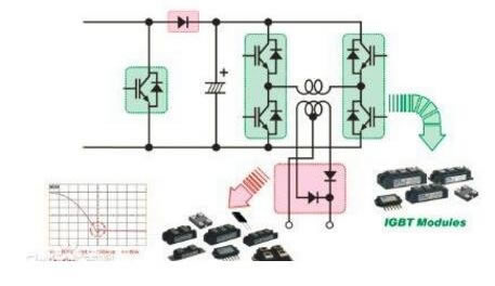
Fast recovery diode (FRD) is a kind of semiconductor diode with good switching characteristics and short reverse recovery time. It is mainly used in switching power supply, PWM pulse width modulator, frequency converter and other electronic circuits, as high-frequency rectifier diode, freewheeling diode or damping diode. The internal structure of the fast recovery diode is different from that of the ordinary PN junction diode. It belongs to the PIN junction diode, that is, the base I is added between the p-type silicon material and the n-type silicon material to form the pin silicon wafer. Because the base region is very thin and the reverse recovery charge is very small, the reverse recovery time of fast recovery diode is short, the forward voltage drop is low, and the reverse breakdown voltage (withstand voltage) is high.
Fast Recovery Diodes: classification, structure and function
Fast recovery diode is one of the high frequency diodes in rectifier diodes. It has a short reverse recovery time, which is especially suitable for high frequency rectifier. The following section introduces the classification, structure, function and performance of fast recovery diodes?
Classification and structural characteristics of fast recovery diodes
Fast recovery diode judgment
High power fast recovery diodes with to – 220 or to – 3P package can be divided into single transistor and double transistor. The lead out mode of double tube is divided into common Yang and common Yin.
Application topology:

Fast recovery diode judgment
Structural features
The internal structure of the fast recovery diode is different from that of the ordinary diode. It is composed of p-i-n silicon wafers by adding base region I between p-type and n-type silicon materials. Because the base region is very thin and the reverse recovery charge is very small, not only the TRR value is greatly reduced, but also the transient forward voltage drop is reduced, so that the tube can withstand a very high reverse working voltage. The reverse recovery time of fast recovery diode is usually several hundred nanoseconds, the forward voltage drop is about 0.6V, the forward current is several to several thousand amperes, and the reverse peak voltage can reach several hundred to several thousand volts. The reverse recovery charge of the ultra fast recovery diode is further reduced, making its TRR as low as tens of nanoseconds. Fast recovery and ultra fast recovery diodes below 20A are mostly packaged in TO-220. From the internal structure, it can be divided into single tube and double tube. There are two fast recovery diodes in the pair tube. According to the different connection methods of the two diodes, there are common negative pair tube and common positive pair tube. Figure 2 (a) shows the outline and internal structure of c20-04 fast recovery diode (single transistor)( b) Figure (c) and figure (c) respectively show the configuration and configuration of c92-02 (common cathode pair transistor) and mur1680a (common anode pair transistor) ultrafast recovery diodes. They are all packaged in TO-220 plastic
Fast recovery diodes with tens of AMPs are usually packaged in to-3p metal case. The larger capacity (several hundred to several thousand a) pipe is packaged by bolt type or plate type.
Fast recovery diode function?
Its internal structure is different from that of ordinary diodes. The p-i-n silicon wafers are formed by adding base region I between p-type and n-type silicon materials. Because the base region is very thin and the reverse recovery charge is very small, not only the TRR value is greatly reduced, but also the transient forward voltage drop is reduced, so that the tube can withstand a very high reverse working voltage. Its reverse recovery time is usually several hundred nanoseconds, forward voltage drop is about 0.6V, forward current is several to several thousand amperes, and reverse peak voltage can reach several hundred to several thousand volts. Its reverse recovery charge is further reduced, so that its TRR can be as low as tens of nanoseconds. It has a positive conduction voltage drop of 0.8-1.1v, reverse recovery time of 35-85ns, and it can switch quickly between on and off, The frequency and waveform of the device are improved. High switching speed and high voltage can be obtained by using gold doping and simple diffusion in the manufacturing process of fast recovery diode. At present, fast recovery diode is mainly used as rectifier in inverter.
How to judge the quality of fast recovery diode?
Place the multimeter in the Rx1k block to measure the forward and reverse resistance of the fast recovery diode. The forward and reverse resistance are generally several ohms and the reverse resistance is 0. If the measured resistance values are or 0, the damaged tube is indicated.The tube detection method for fast recovery diodes is basically the same as that described above, but it is necessary to first determine which pin is the common end of the fast recovery diode, and then use the above method to detect each fast recovery diode.
Example: Measure a C90-02 Ultra Fast Recovery Diode with the main parameters trr=35ns, Id=5A, IFSM=50A, VRM=700V.Look the same (a).Dial the 5 million meter to R&TImes;1, read forward resistance 6.4_, n'=19.5 grid;The reverse resistance is infinite.VF=0.03V/lattice&TImes is further obtained.19.5 = 0.585V.Prove that the pipe is good.
Use precautions
1) Some single-tube, three pins, with empty feet in the middle, are usually cut off at the factory, but some are also cut.
2) If one of the pipes is damaged, it can be used as a single pipe.
3) R&TImes must be used when the pressure drop of the alignment guide is measured;File 1.If R&TImes is used;In 1k, the measured VF value will be significantly lower because the test current is too small and far below the normal working current of the tube.In the above example, if R is chosen×When measured at 1k, the forward resistance equals 2.2k, where n'=9 grids.The calculated VF value is only 0.27V, which is much lower than the normal value (0.6V).


